Compensating and thermocouple cables
General
The voltage of the thermocouples is defined at the zero point. Therefore, thermocouples must not be connected to a normal voltage cable made of copper. This would lead to measurement errors. Consequently, special cables must be used for thermocouples. These are usually called compensating cables.
Their thermoelectric voltage is identical to that of the connected thermocouple up to ~200 °C. For ranges above 200 °C, the original alloys of the thermocouples should be used wherever possible.
It is important to know that the materials of the cables, as with the thermocouple, are different. Therefore, the correct polarity must be ensured. To make things easier, the insulation layers are made in the same color as the thermocouples.
Sheath materials
Thanks to modern electronics, the resistance of the cable is insignificant. Therefore, requirements for the cross-section are practically non-existent. Common cross-sections are 0.22 mm² or 0.5 mm².
The structure of the insulation follows the local circumstances. Consequently, there is a huge variety of versions of sheath materials. Four common materials are:
Polyvinyl chloride (PVC)
This is relatively cheap, flexible and is used up to ~100 °C.
Silicone
Compared to PVC, this material is a little pricier, but has much higher flexibility and temperature resistance up to ~180 °C.
Polytetrafluoroethylene (Teflon™)
This material is characterized by a very high-temperature resistance of ~240 °C. It is also resistant to many chemicals. Compared to PVC and silicone, PTFE is less flexible.
Glass fiber
In areas with high temperatures > 200 °C, insulation made of glass fiber is also used. This can be stable up to 600 °C. However, it tends to become brittle over time. Consequently, these cables should exclusively be used for permanently installed cables.
Shielding
Hardly any design results in errors as often as shielding. This is typically made from a copper braid that is braided around the insulation. In practice, this rarely proves to be effective. Our recommendation would be to avoid shielding and to lay the cables through metal pipes.
If shielding is used, it is necessary that it does not come into contact with the thermocouple. This typically leads to leakage currents and strange behavior.
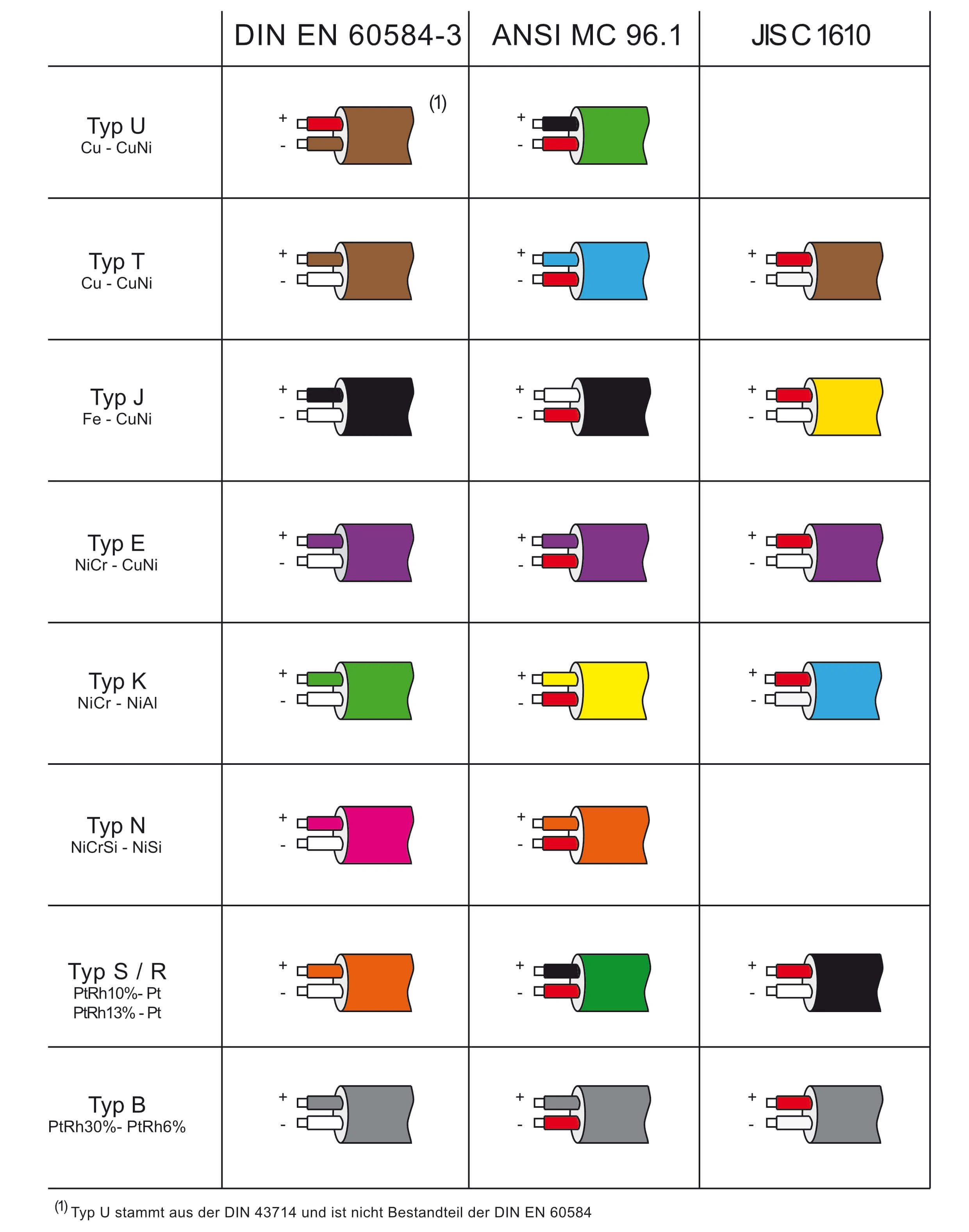

| Type | Positive | Negative |
|---|---|---|
| T | Cu | CuNi |
| J | Fe | CuNi |
| E | NiCr | Ni-Alloy |
| K | NiCr | Ni-Alloy |
| S / R | Cu | Ni-Alloy |
| B | Cu | Cu |
| N | NiCrSi | NiSi |

